 today 134
today 134
today 134
Developing and testing technology components for the machines of tomorrow requires testing under conditions close to reality. Used as a carrier vehicle, Plasser & Theurer’s EM100VT provides the ideal research environment for innovative leaps in technology with a great application potential.
In a few years’ time, the developments in measuring and recording technology could be used on every track maintenance machine.
Florian Auer
Director of Technology and Innovation Plasser & Theurer
Using the vehicle, developers test new technologies under real conditions during regular measuring runs. Data is collected and verified. The results obtained are used to improve the new systems. The real conditions on site (light, ballast condition, obstacles, etc.) cannot be simulated in the laboratory. Experience from practical operation makes it possible to integrate them at an early stage to develop systems for daily operation on railways.
Planning data needed for maintenance work and track renewal has to be collected during line inspections and measuring runs. This involves walking along the line with a measuring wheel to complete an obstacle list and taking photos to document the situation in the track. The resulting document is edited and provides an important basis for maintenance planning. Other tables, CAD plans and further documents complete the documentation.
We are developing new tools for the comprehensive recording of the track infrastructure (track, overhead line, track surroundings). Many features have been integrated into the EM100VT and are tested in practical operation. VT stands for virtual track.
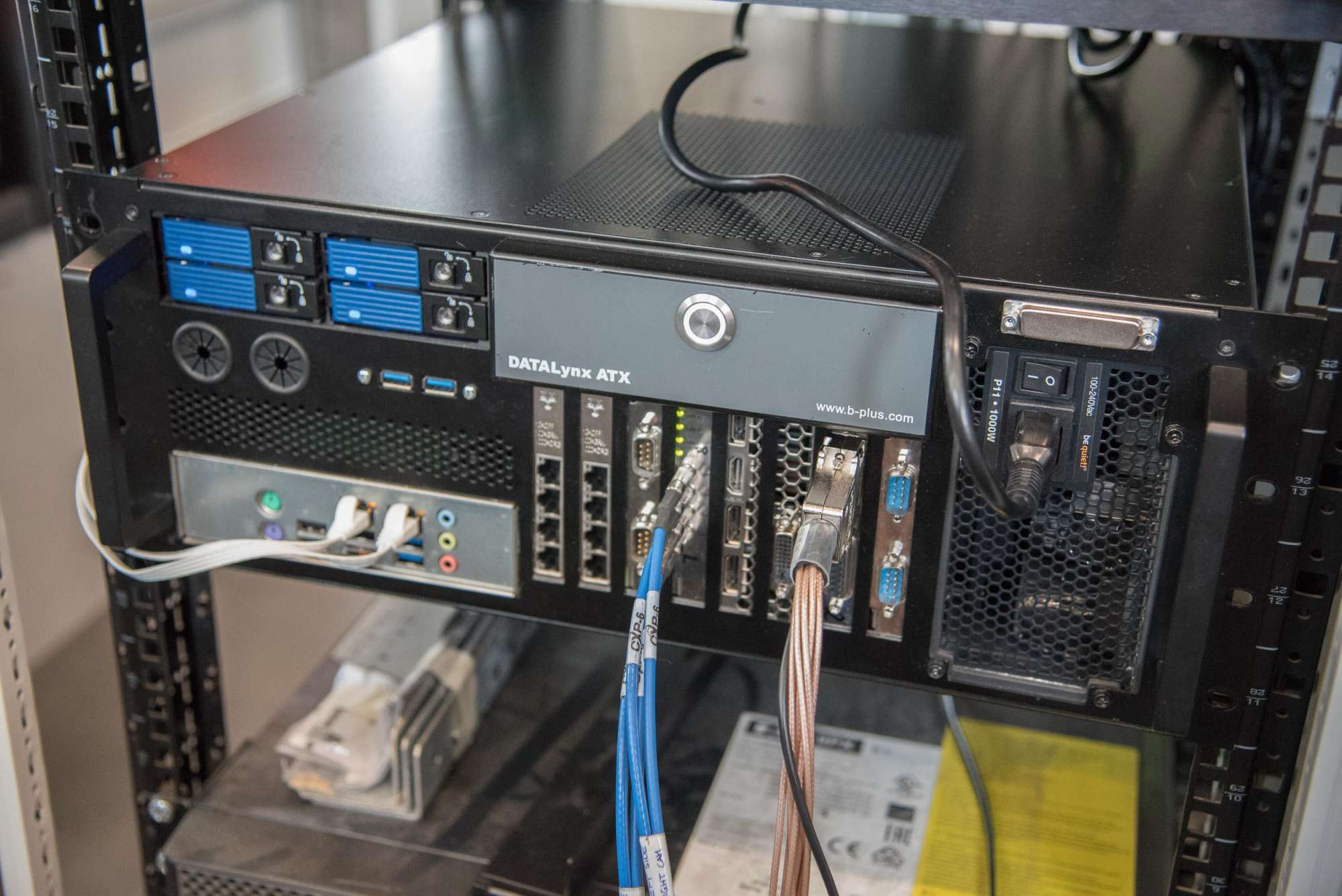
The vehicle is used as a development platform, providing an important basis for digital product development. Numerous measuring components are already in operation. Other components are under development or in test mode. In the second half of 2018, the systematic recording and digitalisation of the track will become a reality.
Currently, the EM100VT is used for the testing of diverse new developments in combination with our well-known measuring equipment.
Used on most of our EM series track inspection vehicles (see box), our well-known measuring system records the track geometry.
The non-contacting track geometry measuring system with integrated GPS navigation and optical gauge measurement (dual OGMS) records the track geometry and generates relative 3D space curves.

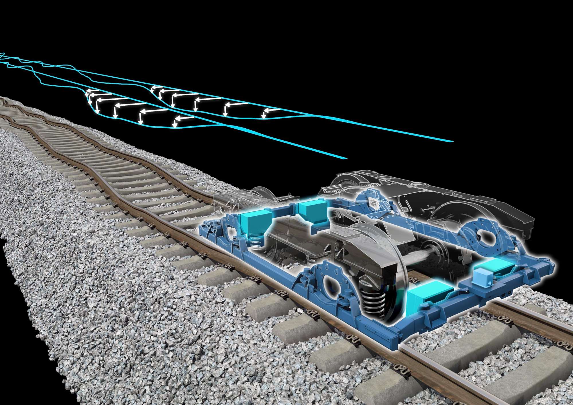
The standard equipment of every track inspection vehicle made by Plasser & Theurer comprises our measuring bogie. It has contributed significantly to the mechanisation and automation of measuring, recording and analysing the track geometry. This measuring equipment has increasingly been integrated into tamping machines, such as the Unimat Combi 08-275, used for spot fault repair in Italy.
The measuring bogie is equipped with a measuring frame which is fixed to the four axle bearings. The IMU inertial measuring unit and the four measuring sensors of the dual track gauge measuring system (Dual OGMS) are mounted on the measuring frame. The entire structure is in extremely sturdy design. This design ensures that the measuring frame, the IMU and the sensors are always guided parallel to the rail surfaces. Therefore, the measuring frame can be used as a reference plane for the track geometry measurement.
As the bogie applies a load to the track during the measuring run, the track geometry is measured under realistic loading conditions. It is not necessary to compensate for suspension deflections or vehicle body movements. The measuring system provides utmost precision from standstill up to maximum vehicle speed.
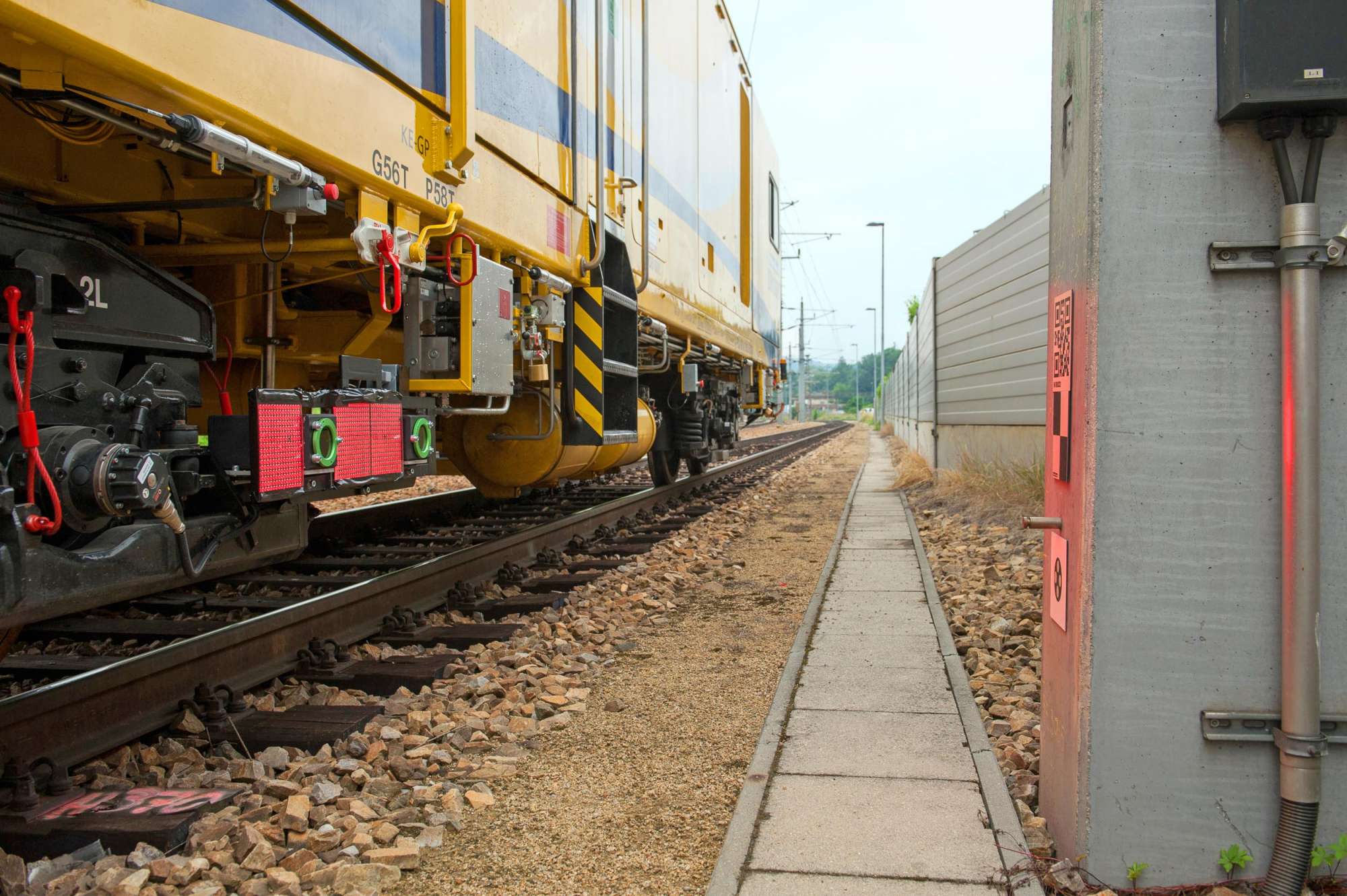
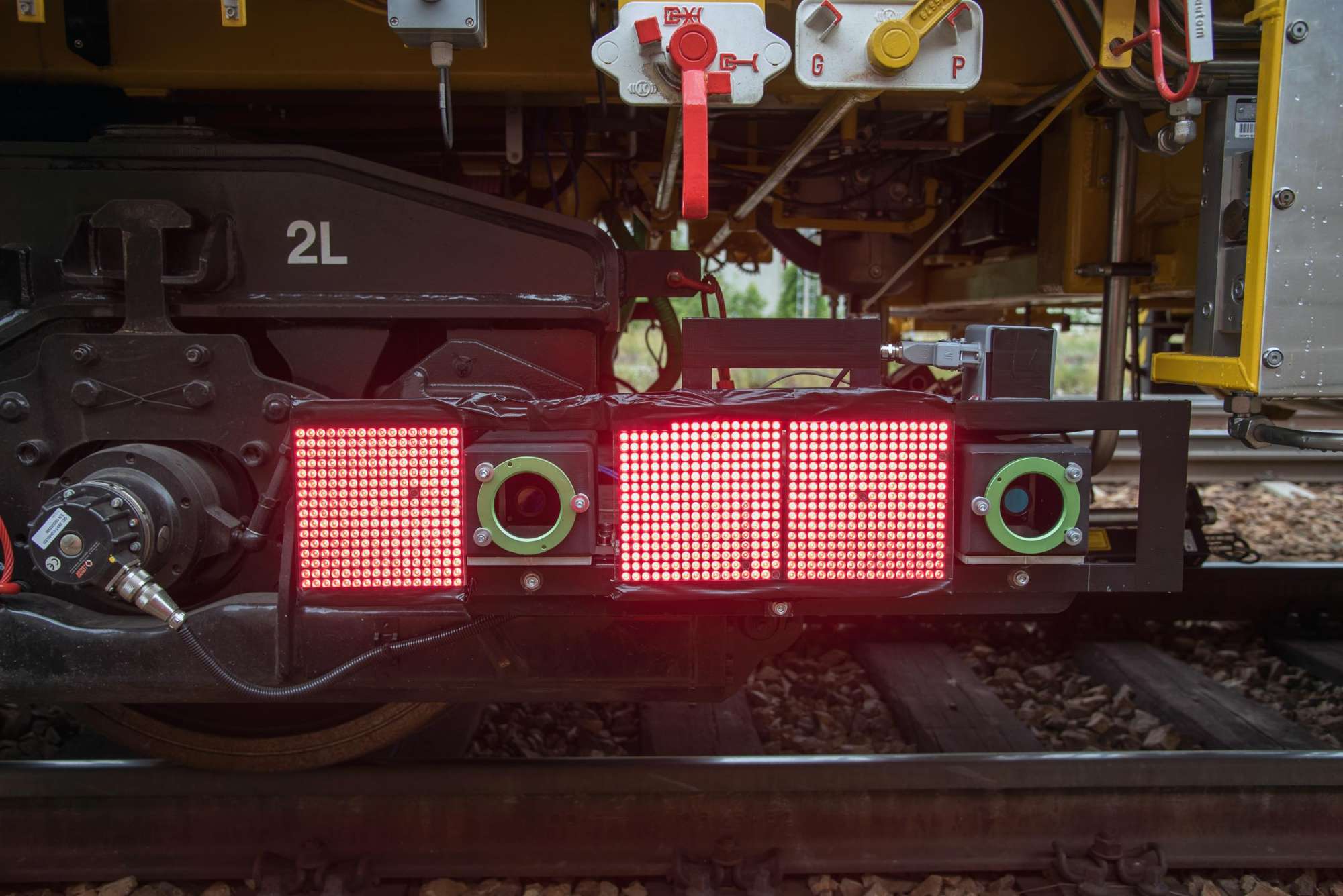
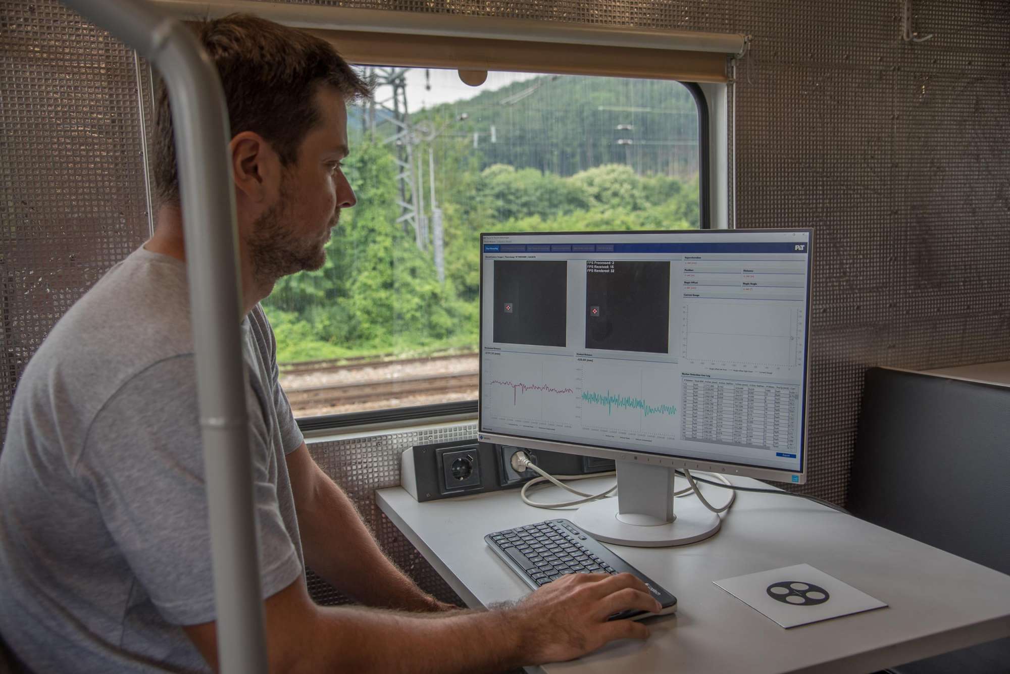
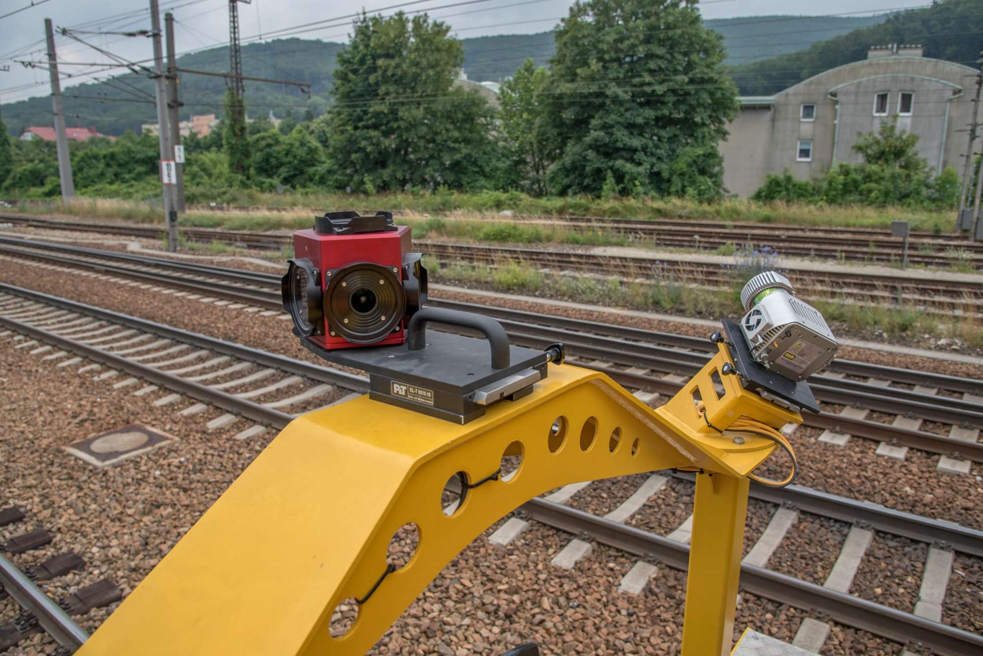
New graphic reference points are recorded by stereo cameras on the vehicle’s side at speeds of up to 100 km/h. LED light panels ensure a standardised lighting situation (exactly adjusted beam angle, wave-length, etc.) for the two special cameras. The position of the fixed points (height, distance) is calculated in real time. Given the frame rate of up to 200 frames per second and a resolution of 5 MB, a large amount of data must be processed and synchronised all the time. Only the data that is actually needed is stored permanently.
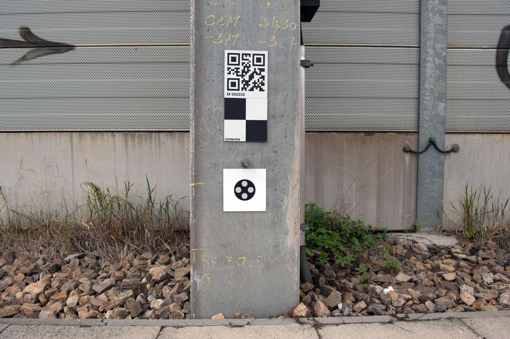
For the reference points, we tested various materials and graphic patterns. Now, the surface is retroreflective. As a result, the incident radiation is reflected to the radiating source or the camera. Light from other sources, i.e. the sun, causes as little interference as possible. The new reference points can also be used as synchronization points for the regular compensation of the IMU (drift compensation).
Starting in autumn, we will test the measuring system during test runs in Italy, gaining valuable experience from practical operation. Rete Ferroviaria Italiana (RFI), infrastructure manager of the Italian State Railway, operates a fleet of Unimat Combi 08-275 spot fault repair machines. Fitted with our measuring bogie, the machines are ideally suited for testing the new fixed-point measuring system.
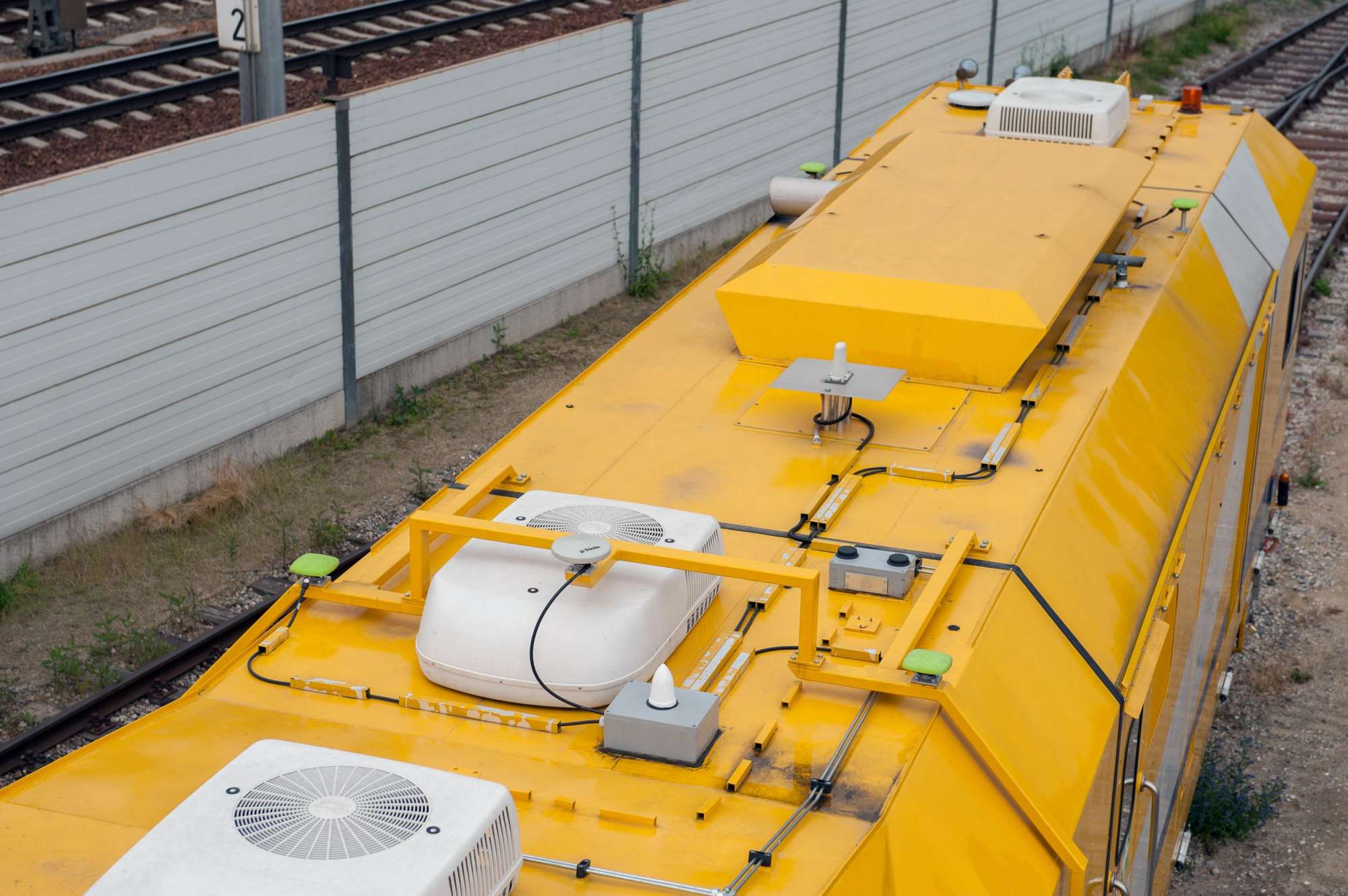
For the first time, a new multi-antenna measuring system for the location of the GNSS/GPS position will be used on the EM100VT. In practical operation, we test how the further developments in satellite-based measuring can be used to locate the track’s position with millimetre precision. In addition, we test the precision of Galileo, the European Satellite Navigation System which is under development.
The location system is suited for speeds of up to 100 km/h, using four GPS antennas in total. To ensure high precision, the antennas are decoupled from the elastically suspended cabin housing of the carrier vehicle. Mounted on a separate frame, they are firmly connected to the machine frame.
The main antenna is a standard feature of our inertial measuring system. Four additional antennas significantly increase the precision of the location result. That is why the GPS reference is much more precise and the data quality is improved.
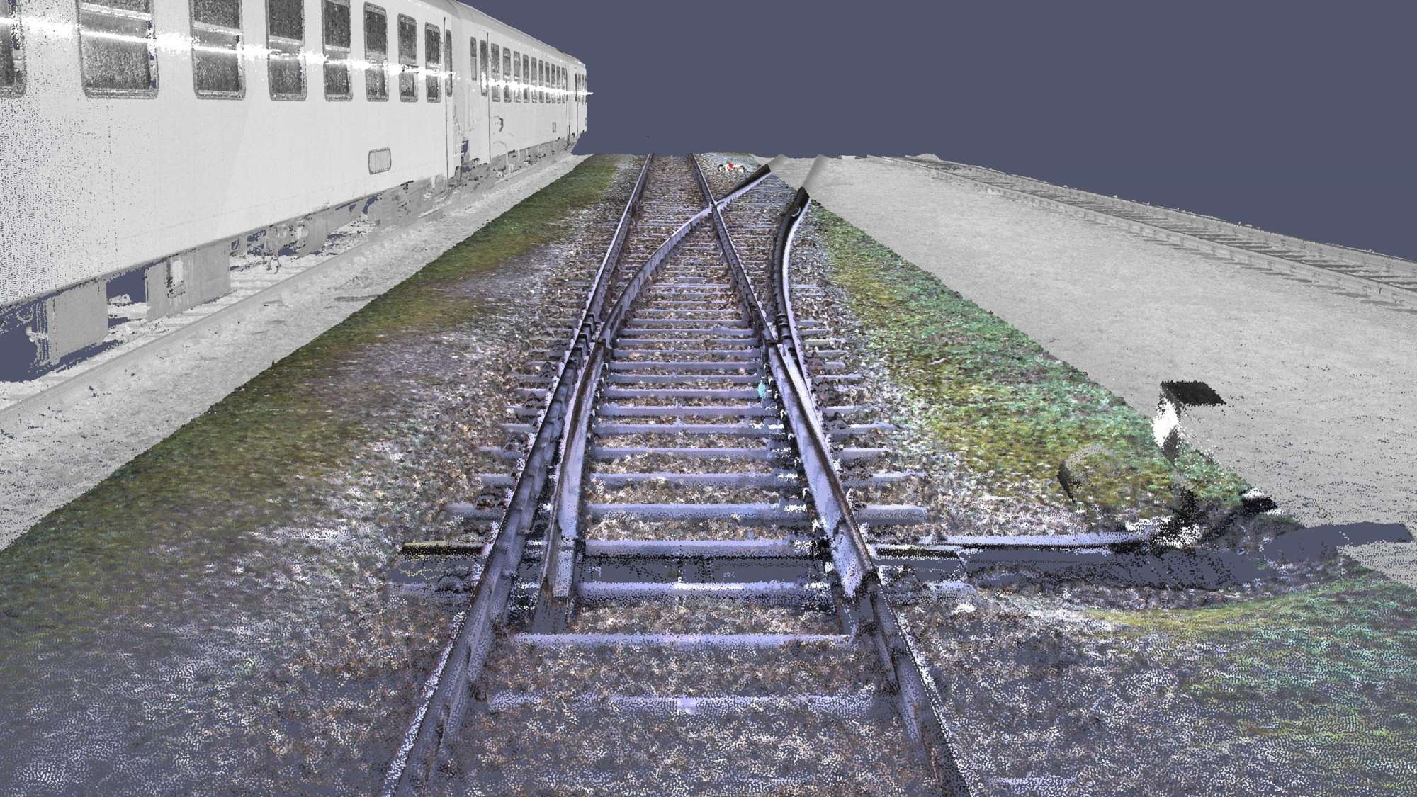
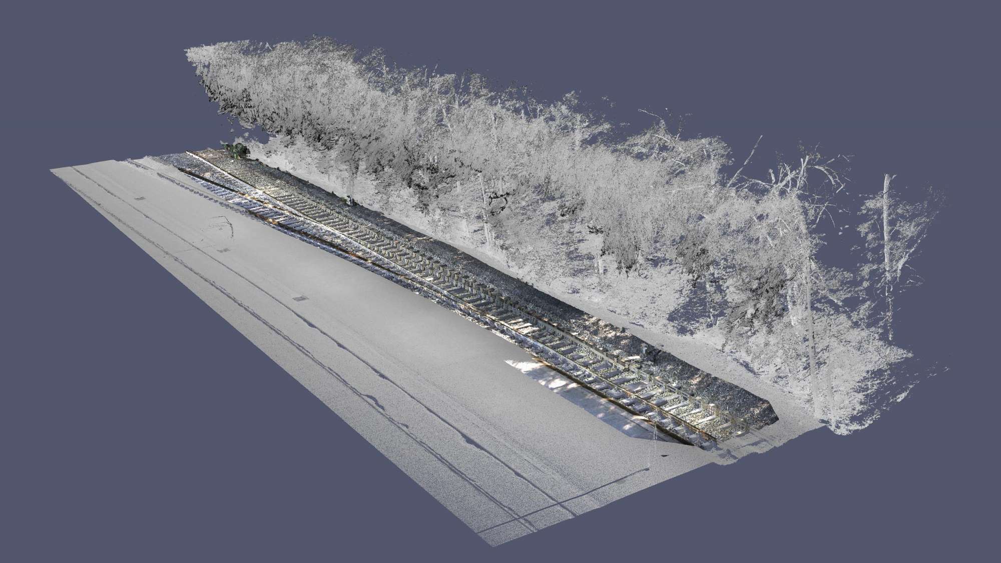
We use various technologies for 3D data collection (mobile mapping):
Two rotating laser scanners with a measuring data rate of one million points per second generate a high resolution 3D point cloud in grey. Each scanner works at 250 rotations per second, producing 250 scans per second.
A rotating colour scanner generates an exact 360-degrees colour image, matching the scans.
Mobile mapping is a highly efficient process for the collection of 3D data. The position of the scanners and the incline of the scanning planes make it possible to exactly scan even vertical surfaces next to the track. Artificial intelligence is used to identify objects in the point clouds.
The data collected will be made available to the digital twin. For this purpose, the outer track geometry (fixed points) and the inner geometry (track geometry, space curves) are compared to the GPS/GNSS data. This comparison further increases data accuracy.
The International Union of Railways (UIC) has developed a network model for the global exchange and global use of railway infrastructure data: the RailTopoModel.
It is a conceptual, comprehensive model. Its structural description makes it possible to support several railway applications in one data model. The most important applications for the simplified exchange of data include:
The RailTopoModel aims to ensure the fast and efficient exchange of data between the individual participants in the railway sector.
Data collection and data processing for the digital twin works on the high-precision nano level of the RailTopoModel.